Specifications:
Video bandwidth: Single-link 165Mhz [ 4.95Gbps]
Video Support: 480i/480p/720p/1080i/1080p @60
Audio Support: Surround Sound [up to 7.1ch] or stereo
digital audio
Transmission Range: HD [ 1080p 24-bit color]-up to 50m [ 164ft]
Input TMDS Signal: 3.3 volts
Input DDC Signal: 5.0 volts/P-P
ESD Protection: Human Body model:+/-8kV [ air-gap discharge]
+/-4kV [ contact discharge]
HDMI connector: Type A 19 pin female
RJ-45 connector: WE/SS 8P8C
3.5mm connector: [ TX and RX] IR Receiver/IR Blaster
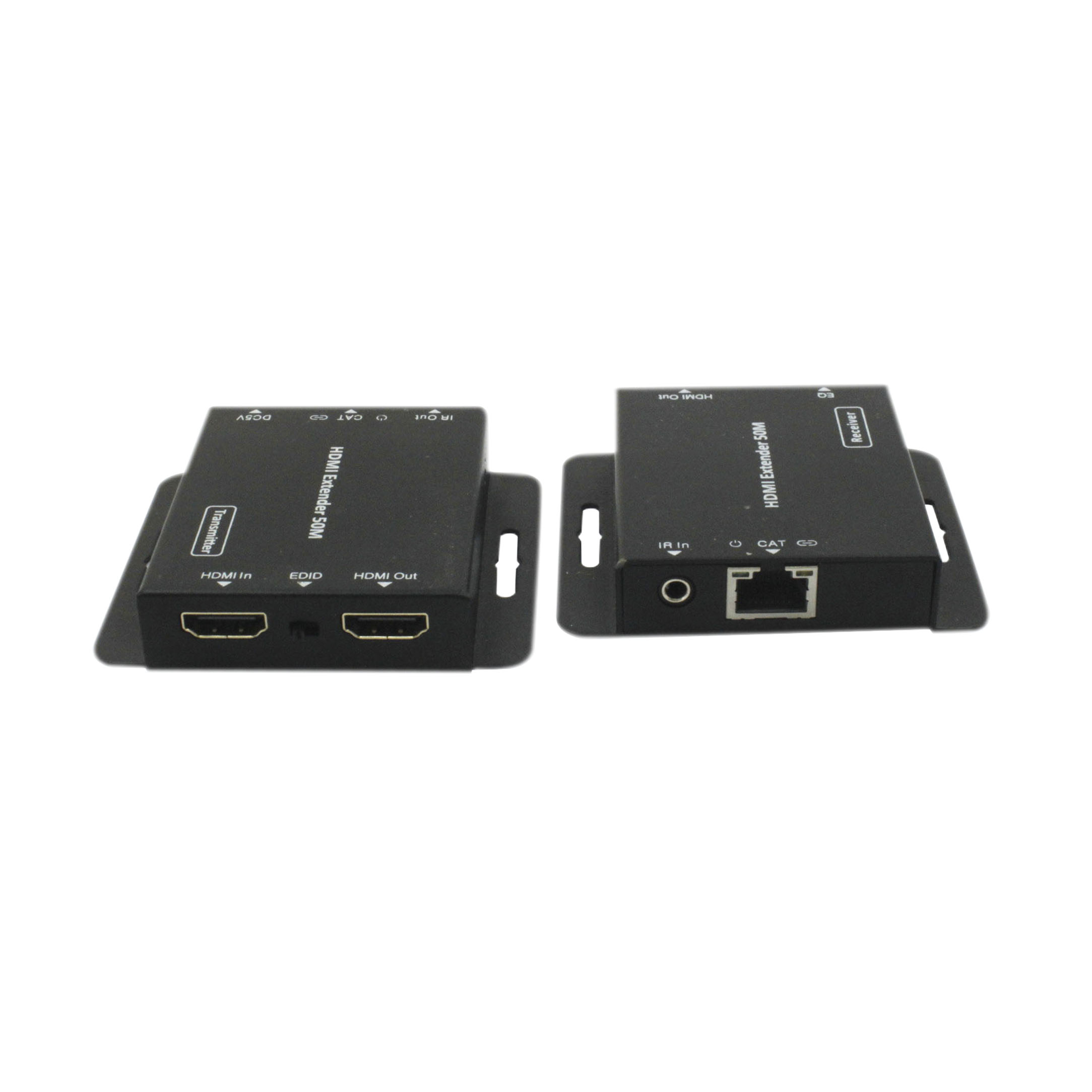
MECHANICAL SPECS
Housing: Metal enclosure
Power Supply: [1]5V1A DC
Power consumption: 1.5 watts [ TX];1.0 watts[ RX]
Operation temperature: 32~140ºF
Storage temperature: -4~140ºF
Relative humidity: 20-90%RH(no condensation)
Panel descriptions:
1. Transmitting unit
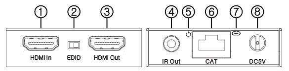 ①HDMI in:
 This slot is where you connect the HDMI output
port of your source equipment such as DVD/Blu-ray
players or Set-Top-Box with an HDMI cable.
②EDID: The switcher can switch copy EDID function, switch to right
position, the extender will copy hdmi loop out display EDID
information to source. Switch to left position, the extender
will copy Receiver display EDID to source
③HDMI out: This slot is to connect the HDMI input of your display
such as an HDTV
④IR out: Connect the IR Blaster cable included in the package for IR
signal transmission. Pace the IR blaster in direct line-of-sight
of the equipment to be controlled
⑤Power LED: This LED will illuminate when the device is connected
with power supply
⑥CAT: Connect the CAT output of the transmitter with the CAT input of
the receiver with CAT5E/6 cable
⑦Link LED: This LED will illuminate when the device is connected to
HDMI source
⑧DC5V: Connect from 5V DC power supply into the unit and connect
the adaptor to an AC outlet.
2. Receiver unit
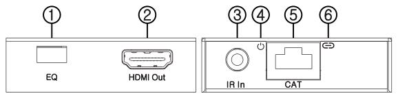 ①EQ switcher:
 HDMI Receiver equalizer switcher
②HDMI out: This slot is to connect the HDMI input port of your
Display such as an HDTV
③IR in: Connect to the IR Receiver for IR signal reception.
Ensure that remote being used is within the direct line-of-sight
of the IR receiver.
④Power LED: This LED will illuminate when the device is connected
with power supply
⑤CAT: Connect the CAT input of the receiver with the CAT output of the
Transmitter with CAT5E/6 cable
⑥Lock LED: This LED will illuminate when the HDMI signal from the
Transmitter is stable.
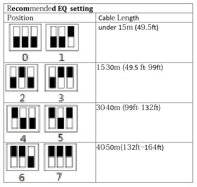
3.RX Equalizer distance adjust
If you see ?lickering or blinking image on th display, adjust the EQ
switch to improve the cable skew. MAX stands for th strongest HDMI
signal level for the longest possible transmission length while MIN
stands for the weakest HDMI signal level for short transmission length.
Adjust the signal level from MIN to MAX until desired video quality is
displayed.
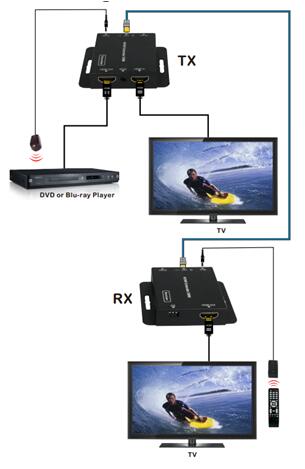
 Connect and Operate:
1.
Connect and Operate:
1.Connect a source such as a Blu-Ray Player, game console, A/V Receiver,
Cable or Satellite Receiver, etc. to the HDMI input on the Transmitting unit.
2.Connect a display such as an HDTV or HD Projector to the HDMI output
on the Receiving unit.
3. Connect a single Category 5e/6 up to 164ft/50m to the output of the
transmitting unit, and the other end to the input of the Receiving unit.
4. For power, plug both the Transmitting unit and Receiving unit with the
included power supplies.
5. Power on each device in the same sequence (receiver and transmitter will
already be powered when either unit is plugged in.)
At this point the display connected should display the source signal connected
to the extender set. If no signal is being displayed, check the receiver EQ
switcher. If a display is having difficulty receiving a signal, see EDID section
and perform EDID learning or access the display's menu and adjust the
resolution(lowest to highest until signal is displayed). A 24 Hz vertical refresh
rate may work better than 60 Hz o higher. Use the source remote at the receiver
emitter to test IR functionality. If the IR remote function is not responding, check
the emitters to ensure they are placed correctly and are plugged into the correct
IR jacks on the Extender set receiving and transmitting units.
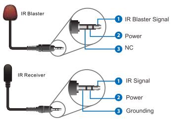
Wideband IR(30KHz---60KHz) introduction
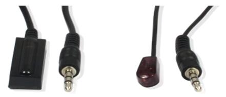
IR RECEIVER IR BLASTER
IR BLASTER (TX)
To control the source: Plug IR Blaster into IR TX port transmitter unit; place blaster
in front of the IR eye of the source
IR RECEIVER (RX)
To control the source: Plug IR Receiver into IR RX port of receiver unit; place receiver
at or near display.
 Application