


 |
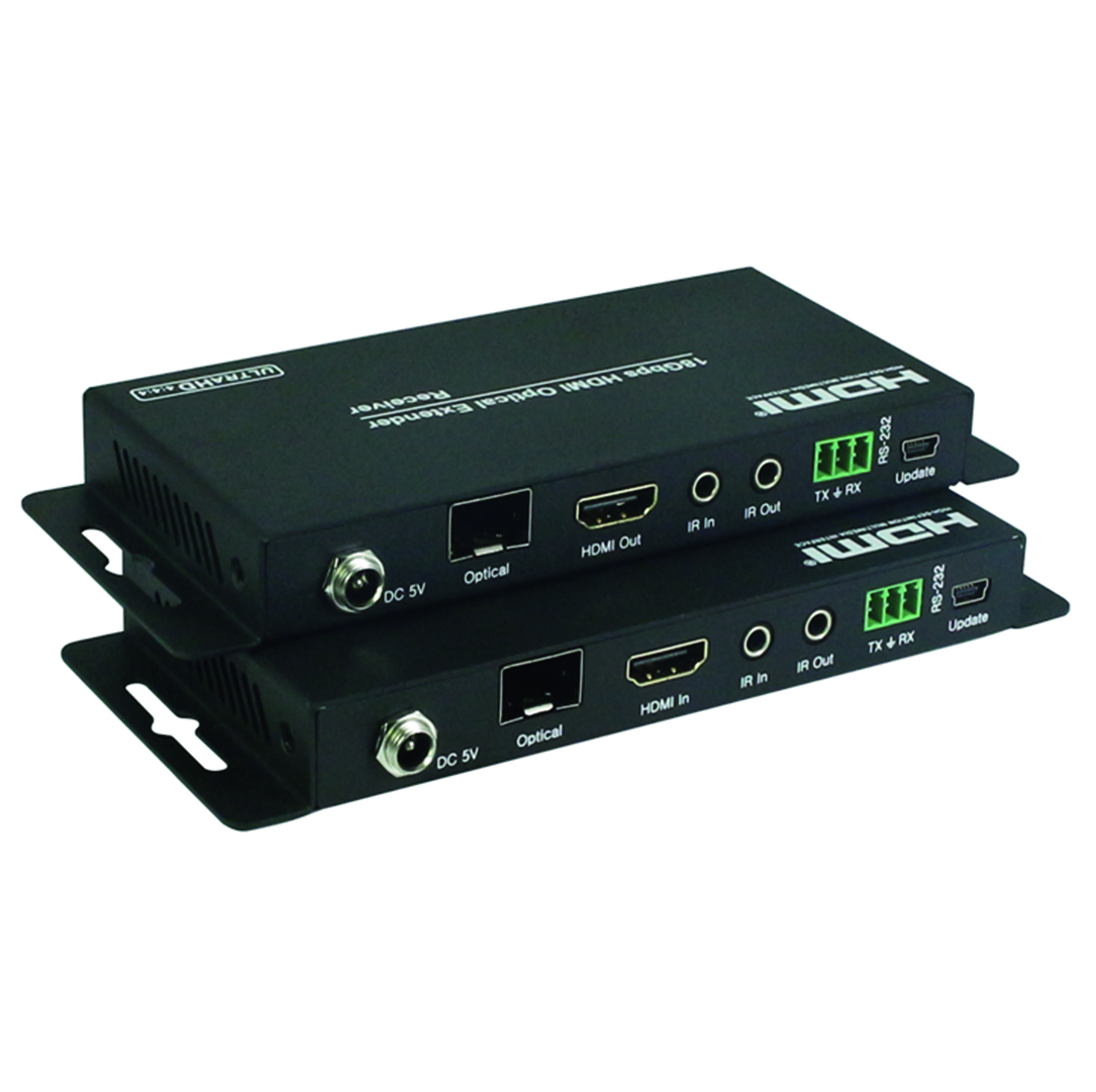
STR001F-HDVHDMI over Optical Fiber Extender
Features:> HDMI 2.0b (18Gbps), HDCP 2.2 and DVI compliant> Video resolutions up to 4K2K@50/60Hz (YUV444) > Audio supports LPCM2/5.1/7.1 CH, Dolby Digital, DTS, Dolby True HD, DTS-HD Master Audio > Long distance transmission up to 3300 feet/1000 meters over single-mode fiber cable and up to 1000 feet/300 meters over multi-mode fiber cable ( 50/125µm/OM3) > Bi-directional wideband infrared control and RS-232 transmission > Locking power supply |
| Technical | |
| HDMI Compliance | HDMI 2.0b |
| HDCP Compliance | HDCP 2.2 and HDCP 1.4 |
| Video Bandwidth | 18 Gbps |
| Video Resolutions | Up to 4K2K@50/60Hz(YUV4:4:4),4K2K@30Hz,1080P@120Hz, and 1080P 3D@60Hz |
| Color Space | RGB, YCbCr 4:4:4, YCbCr 4:2:2 |
| Color Depth | 8-bit, 10-bit, 12-bit |
| HDMI Audio Formats | LPCM 2/5.1/7.1CH, Dolby Digital, DTS 5.1, Dolby Digital+, Dolby TrueHD, DTS-HD Master Audio, Dolby Atmos, DTS:X |
| Operation Range |
Up to 3300 feet/1000 meters over single-mode fiber cable Up to 1000 feet/300 meters over multi-mode fiber cable |
| IR Frequency | 20KHz - 60KHz |
| RS-232 Baud Rate | 4800-115200bps |
| ESD Protection | Human body model — ±8kV (air-gap discharge) & ±4kV (contact discharge) |
| Connections | |
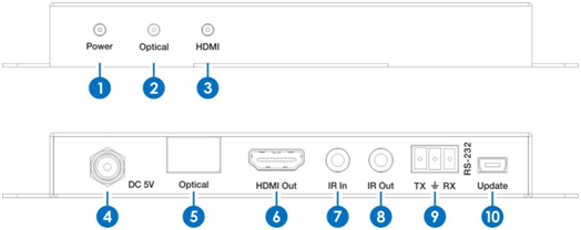
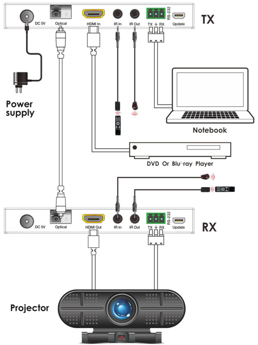
| Transmitter |
Inputs: 1x HDMI Type A [19-pin female] 1x IR In [3.5mm Stereo Mini-jack] 1x RS-232 [3.81mm Phoenix connector] Outputs: 1x Optical Fiber Out [LC female] 1x IR Out [3.5mm Stereo Mini-jack] |
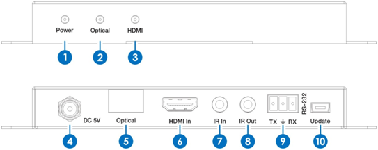
| Receiver |
Inputs: 1x Optical Fiber In [LC female] 1x IR In [3.5mm Stereo Mini-jack] Outputs: 1x HDMI Type A [19-pin female] 1x IR Out [3.5mm Stereo Mini-jack] 1x RS-232 [3.81mm Phoenix connector] |
| Mechanical | |
| Housing | Metal Enclosure |
| Color | Black |
| Dimensions | 100mm [W] x 65mm [D] x 25.6mm [H] |
| Weight | TX: 256g RX: 260g |
| Power Supply |
Input: AC100 - 240V 50/60Hz Output: DC 5V/1A (US/EU standards, CE/FCC/UL certified) |
| Power Consumption | 3W (Max) |
| Operation Temperature | 32 - 104°F / 0 - 40°C |
| Storage temperature | -4 - 140°F / -20 - 60°C |
| Relative Humidity | 20 - 90% RH (no condensation) |

| Class | Date | Title | Download |
|---|


Copyright © 2017 Anxing Security